CTC-teknik i början av 1930-talet
Under åren 1931 - 1935 pågick inom SJ en utredning om CTC,
alltså fjärrstyrning av trafiken, på sträckan Malmö
- Trellleborg. I samband med detta inkom till SJ följande beskrivning
från Westinghouse. I första hand är det väl CTC-system
från Union Switch som beskrivs; Westinghouse samarbetade med US&S
och agerade i Sverige via Signalbolaget. Beskrivningen är anpassad
till brittiska förhållanden; det talas exempelvis om ground
frames (ungefär centrallås för lastplatser mm) och "Tube"
or "Underground" railways.
Den CTC-installation vid Stanmore som nämns, blev slopad redan i slutet
av 1930-talet, i samband med att banan byggdes om. CTC passade inte in i det
nya London Transports standard för signalsäkerhetsanläggningar.
Den konkurrerande tillverkaren GRS ansåg sig ha patent på vissa
konstruktioner som ingick i CTC-systemet, och stämde Westinghouse för
Stanmore-installationen. Det slutgiltiga domstolsutslaget, som innebar att
GRS inte hade något sådant patent, kom inte förrän Stanmore-anläggningen
avvecklats.
Dokumentet ingår i ärendet Bbrsi 240/42, som finns i volym
Bbrsi EI:13 i riksarkivet, Arninge.
C.T.C
DESCRIPTION NO. J.173
Circuit Code and Time Code Systems
I. General Survey.
II The Circuit Code System.
III. The Time Code System.
IV. Application of the Cirouit Code System.
V. Application of the Time
Code System.
VI. The Control Machine and Auxiliary
Apparatus
.
Appendix A. C.T.C. Definitions.
B Relay Nomenclature.
Circuit Code System.
C. Relay Nomenclature, Time Code System.
D. Code Unit Dimensions
THE WESTINGHOUSE BRAKE & SAXBY SIGNAL CO. LTD. 82,
YORK ROAD. KING'S CROSS, LONDON, N.l.
Centralized Traffic Control
Code System
PART I.
The name Centralized Traffic Control (C.T.C.) is given to a system whereby
all points, signals, switch looks or other functions to be operated
at a distant location or series of locations are brought under the control
of an Operator at a central point. The name also implies the use of
a special system of control and also of a kind that is distinct from systems
usually employed for the control and indication of functions close to the
control point.
At the present time two different systems can be employed for the control
of functions close to the control point. Firstly there is the type of system
using some form of interlocking machine or power frame where mechanical or
electrical lever interlocking is provided. Secondly, there is
the type where direct interlocking between levers is not employed and where
all interlocking between functions is carried out by means of circuits
between relays - a Relay Interlocking as distinct from a Lever Interlocking.
C.T.C. .is not another type of relay interlocking, but it is a scheme
for the distant control of relay interlocking.
C.T.C. systems can themselves be divided into two types, namely Code systems
and Multiwire or Direct Wire Systems. Each type has its uses and as
a general rule the code systems are the most flexible and have the widest
field of application.
The first coded installation of C.T.C. was placed in service on the Pere
Marquette R.R. in U.S.A. in 1928. Since that date, C.T.C, has continued to
grow, and up to july 1933, over 900 miles of road with 800 power points and
2,000 controlled signals were under C.T.C. oontrol in the U.S.A. Installations
have also been brought into service in Canada, England and France, and are
pending in other countries,
Originally C.T.C. was intended to supersede the Train Order System then
in force on single lines with passing loops, but during the succeeding years
the system has been applied to almost every kind of railway layout and every
type of traffic. The installation between Peru & State Line on
the Wabash R.R. (U.S.A.) is the longest installation, and here the most distant
pair of points is 93 miles from the Control Office. It is also interesting
to note that the control machine is placed in the Railway Offioe buildings
about 1/2 mile from the railway itself. The Pennsylvania R.R. have
installed C.T.C. between Limedale and Ben Davis, a distance of about 30.3
miles. The traffic between these points is extremely heavy, practically all
the passenger trains have fast achedules, and cover the distanoe in one direction
in about 30 mins. and in the other in 32 mins. The freight tonnage handled
amounts to 86,558 gross ton miles per train hour, and the trains are for
the most part fast and run at speeds up to 50 m.p.h.
The recent installation in Franoe at Sartrouville on the Chemins de Fer
de l'Etat can be quoted as an example of C.T.C. applied to the control of
intense surburban traffic
The introduction of C.T.C. has avoided the construction of quadruple tracks
between Houilles and Sartrouville, and only one new track has been added.
The third track is signalled for reversable working, and the signals on this
track, together with the signals and points in the original two roads, are
controlled from an office at the Gare St. Lazare about 14 km. distant.
The Stanmore installation of the London Passenger of C.T.C. to branch
lines carrying heavy traffic. At the present time, about 96 trains
in each direction per day with several additional freight trains are being
handled by the installation.
The C.T.C. on the Philadelphia Subway is subjected to exceptionally heavy
duty, and it is estimated that ultimately no fewer than 21,000 codes will
be sent and received each working day.
These few typical installations will serve to illustrate the diversity
of application of C.T.C. Code systems, and it may be noted that where figures
are available, savings of between 13 % and 47 % have been realized, and these
figures do not include many advantages which cannot always be assessed in
cash.
Turning now to the C.T.C. equipment, two separate code
systems have been developed, one known as the Circuit Code System and
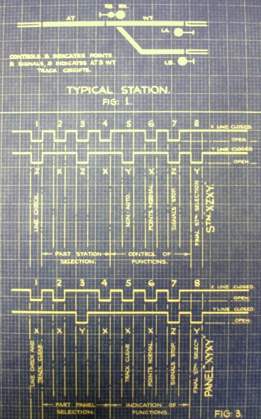
the other as the Time Code System. For the purpose of describing the
capacity of the systems the typical layout or "station" given on Fig.l is
taken as a basis. Thus the Circuit Code System is capable of
handling the control and Indication of 81 such stations over a total of
3 line wires. The Time Code System will handle 35 stations over two line
wires.
The control point need not be in any particular position relative to the
field locations and may be at either end, in the middle, or at any intermediate
point. The position of each field location is fixed by the position of crossings,
junctions, station platforms, etc, the most convenient and economical
location for the field equipment being found by detail consideration of the
scheme. Both the time code system and the circuit code system accomplish
the same operating results and the layout of the control machine is
identical for both systems. It should be noted however, that a complete code
is transmitted in either direction in 3 1/2 seconds with Time Code apparatus,
and in I 1/2 seconds with Circuit Code apparatus.
Before going further it should be stated that C.T.C. does not take the
place of the ordinary signal circuits and does not in any way alter the usual
safety, protection and reliability of such circuits. Each field location
represent a self-contained relay interlocking which may have any or all of
the well-known locking features such as approach locking, route locking,
track locking and back locking.
C.T.C. is superimposed upon these circuits to enable the distant Operator
to control the movements of trains by signal aspects over the crossings and
junctions, but only if such movements are safe. Thus, the Operator may send
any code he pleases but the codes will only be effective if the locking on
the ground permits.In the case of approach locking, the locking is released
by the operation of a release push button in the Office Control machine if
circumstances in the field permit, and then only if the time element release
relay functions for the full time delay period.
The C.T.C. equipment can be divided into two parts -the oontrol machine
and the code units.
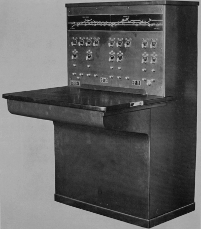
CONTROL
MACHINE, (Time or Circuit Code).
The control machine comprises a sheet-steel cabinet fitted with a front
panel upon which are mounted the levers, push buttons, illuminated track
diagram, and the necessary indication lamps. If an automatic train
graph recorder is to ha provided, it la fitted below the levers on the front
panel and flush with the wooden shelf desk. To enable the pen tracks
to be more easily followed a miniature track diagram is placed just above
the pens.
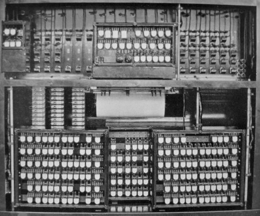
The office code units are housed inside the control machine cabinet, as
illustrated on Fig. 13, for the circuit code system.
 A typical arrangement of the control machine control panel is shown on
Figure 14. An illuminated track diagram is mounted above the levers
and shows the relative position of signals, points and track circuits together
with their reference numbers. Small white or red lamps indicate whether any
track circuit is unoccupied or occupied as on ordinary illuminated diagrams.
The row of miniature levers immediately below the illuminated diagram
are for the control of points and have two operating positions - to the
left for points normal, and to the right for points reverse. White
and green lamps plaoed just above each point lever indicate that the points
are normal or reverse respectively; no light on these lamps indicates
that the points are not occupying either of their proper positions and that
the point detection circuit is broken owing to the point tongues not being
fully over or that the point lock is not right home.
A typical arrangement of the control machine control panel is shown on
Figure 14. An illuminated track diagram is mounted above the levers
and shows the relative position of signals, points and track circuits together
with their reference numbers. Small white or red lamps indicate whether any
track circuit is unoccupied or occupied as on ordinary illuminated diagrams.
The row of miniature levers immediately below the illuminated diagram
are for the control of points and have two operating positions - to the
left for points normal, and to the right for points reverse. White
and green lamps plaoed just above each point lever indicate that the points
are normal or reverse respectively; no light on these lamps indicates
that the points are not occupying either of their proper positions and that
the point detection circuit is broken owing to the point tongues not being
fully over or that the point lock is not right home.
The signal levers are mounted below the point levers and operate in two
or three positions.) the normal (signal danger) position in either case
being vertical. As with the point leveras, signal indication lamps
are provided above eaoh signal lever; when the red indication lamp is illuminated
it la an indication that all signals controlled by the lever are exhibiting
the stop aspect. If either the L or R indication lamp (which may be
green or yellow according to the individual circumstances) is illuminated,
it is an indication that one of the L or R signals la displaying a proeeed
aspect.
The spring return push buttons below the signal levers are usually employed
to bring into operation a time element device in the field for the release
of points if these become approach locked, sometimes these push buttons are
used for other purposes such as the control of the automatic or semi-automatic
working of signals or the control of signal lamps or signal fog-repeaters.
The row of spring return push buttons below the release push buttons are
termed start buttons and the operation of one of these causes a control code
to be transmitted to the field station, and a control code thus started contains
only "controls" selected by the levers and push button located vertically
above it.
The cancel button is placed close to the code indication lamps and its
function is described in detail later.
Any of the indication lamps, levers and push buttons (with the exception
of the start and cancel buttons) described above can be arranged to indicate
or control other apparatus in the field for instance, it is not unusual for
a lever in the top row to be used as a release lever for a ground frame and
its associated lamps to indicate the state of the ground frame levers.
AUTOMATIC
TRAIN GRAPH RECORDER.
The provision of this instrument in the control machine equipment is optional,
but there is no doubt that it forms a very valuable addition to the system.
The Recorder comprises a paper chart which moves along under a series
of pens, each of which traces a straight line on the paper so long as the
traok circuits are unoccupied. When one of the track circuits becomes de-energised,
the corresponding pen will be deflected at the same time as the track lamp
on the illuminated diagram is extinguished, and will remain deflected until
the track circuit clears again. Thus a permanent record is obtained of all
train movements which have taken place in the C.T.C. controlled area and
from the Operator's point of view provides a visual record, from which he
can refresh his memory, of train movements actually going on in his
territory. A sliding glass panel is fitted above the chart so that notes may
be entered on the chart. A typical length of chart is illustrated on Figure
17. and from this it will bo seen that the Operator has drawn diagonal pencil
lines connecting the pen deflections so as to check the relative position
of the trains.
The chart is moved forward by a simple mechanism controlled from contacts
on an electric or other reliable clock and therefore eliminates the elaborate
internal clockwork gear whioh would otherwise be necessary. Another view
of the Recorder will be found in Fig. 16.
CODE UNITS (I. Circuit Code).
The code units contain the apparatus whioh generates and decodes the code
impulses. Three different units are used in the Circuit Code system for the
81 station equipment, namely, the Line Unit, the Coding Unit and the Storage
Unit. The office equipment consists of an Office Line Unit, an Office Coding
Unit and an Office Storage Unit all of whioh are usually mounted inside
the control machine cabinet as illustrated on Figure 13. The Line Unit
will be seen in the top left corner, the Coding Unit to the right at the
top, with the Storage Units below; each horizntal row of relays in the storage
unit represents the equivalent of a field station controlled from this control machine.The Office Line & Coding Units are fitted with a hinge mechanism
so that they may swing outwards to facilitate quick removal and to permit
easy maintenance of the lever and push button contacts. Both these
units provided with detachable terminal racks, (such as that for the field
storage unit illustrated on Fig. 19) to allow speedy change of unit and to
avoid all possibility of wrong connections being made in the wiring. The
office storage units are also mounted on hinges but are not generally fitted
with detachbalbe terminal racks since maintenance can be carried out on individual
relays in this unit without affecting the whole system. All wiring in the
control machine is of a permanent nature, carried out in the Factory prior
to the machine being despatched. Thus, on reaching the site, the only connections
which must be made in order to bring the machine into service are those
from the local 24 V battery, the three line wires and the local A.C. supply
for the indication lamps - a total of seven connections to control machine
terminal board.
The field line and coding Units differ only slightly from the corresponding
Office Units and are also fitted with detachable terminal racks, but have
shock absorbing arubber feet instead of the hinge arrangement. The field
storage unit is illustrated in Fig.19, and it is to this unit that the connections
between the C.T.C. equipment and the standard field signals are made. Each
unit of like name is of standard design (except the office storage unit),
and is interchangeable so that in the event of failure a complete unit may
be changed.
The units are all built on very robust lines, each being constructed of
a sheet steel case fitted with a glass front to allow the relays to be kept
under observation for maintenance purposes. The relays are all of the same
general type, i.e. are all direct current neutral relays, no polar relays
being used in the Circuit Code System, (no other apparatus such as preselectors
or steppers are employed).
Double contact pieces are provided for each relay contact spring and each
contact which may break an inductive load la conneoted to a spark quench
circuit to prevent harmful burning of the relay contacts. The spark quench
circuits are taken through two indicating fuses so that in the event of a
fault occurring in one of the quench units, the lineman may be warned that
some of the relay contacts may, in consequence, be without spark protection.
The main function of each unit is given briefly as follows —
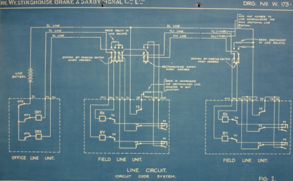
1. OFFICE & FIELD LINE UNITS (8 Station Basis).
These units contain the Office & Field series Line epeater relays
ORX, ORY, RX & RY together with their associated transmitter relays
OTX, 0TY,0TZ, TX, TY & TZ, and therfore handle the actual line impulses.
2. OFFICE & FIELD CODING UNITS (81 Station Basis).
The coding units contain the R & T chain relays which with the line
relays either generate or receive the code impulses. These units also
contain the intermediate station determining relays for station selection,
and the intermediate control relays which store control or indication impulses
until they are passed on to the storage units at the end of a complete code.
Each unit (not generally the Office Storage Units) is provided with the
standard type of detachable terminal rack (see Drg. 194 • 25). The general
construction of the Time Code Units is similar to those described for the
circuit Code Units and here again only D.C. neutral relays are employed in
the code equipment.
The main function of each unit is given briefly as follows
—
1. OFFICE & FIELD LINE-CODING UNITS.
These units contain all the relays (including the line repeater relays)
which are necessary to generate, receive and decode the code line impulses.
2. OFFICE STORAGE UNIT.
The office storage unit contains the code starting relays for each panel
on the control machine and also the lamp indication relays for the point,
signal and track indication lamps for each panel.
3. FIELD STORAGE UNIT.
This unit is provided with a sufficient number of relays to handle the
controls and indications for the typical field station or an equivalent amount
of apparatus. It therefore contains the final stick relays I3P, IIP and 9P,
12P end 10P, which control the point and signal operating relays, etc;
it also contains the necessary starting and indicating relays required to
return indication codes to the office.
OPERATION (Time & Circuit Codes).
Normally apparatus, both at the Office and in the field, is at rest. When
the Operator wishes to make some alteration in the field such as to clear
a signal or reverse a crossover, he will move the appropriate lever and
then press the start button. This last action will initiate a control code
which will both select the proper field unit and energize the control relays.
If conditions in the field permit, the signal (if he has mowed a signal
lever) will clear and in so doing will automatically start the field apparatus
to transmit indication code back to the Office to inform the Operator that
the signal has responded to his control code. Similarly other movements
of the field apparatus such as the occupation of track circuits, end the
position of the points will be indicated continuously on the control machine,
and any alteration in their position will always send a code ox codes to
the Operator to keep him advised as to the state of the apparatus under his
control
---------------------------------------
 steps or impulses, it is possible to do three different things,
namely, de-energize the X line so giving an "X" character to the impulse,
or de-energize the Y line to give "Y" impulse, or thirdly to de-energize
both the X & Y lines, so giving the impulse a "Z" character.
code will therefore consist of eight line interruptions each of which may
have one of the three different characters X, Y or Z.
steps or impulses, it is possible to do three different things,
namely, de-energize the X line so giving an "X" character to the impulse,
or de-energize the Y line to give "Y" impulse, or thirdly to de-energize
both the X & Y lines, so giving the impulse a "Z" character.
code will therefore consist of eight line interruptions each of which may
have one of the three different characters X, Y or Z.
CODE MAKE-UP.
Since there is only one line channel to all stations, it is necessary
in order to select a given station or a particular panel on the office control
machine, that a code must have some distinguishing feature which will
serve to operate the code receiving equipment in such a way that only one
field location or one office panel will respond to a particular code. In
other words, each code must have a station or panel selecting feature
and this is accomplished in the Circuit Code System, by varying the character
of four of the eight impulses. Since each of these four impulses can be given
one of the three different characters, it follows that with this arrangement
it is possible to obtain 81 different station selecting combinations, viz.
XXXX, XXXY, XXXZ, XXYZ, XXYY, etc. etc. In addition to
the station selection steps, it is also necessary to provide a distinction
between an outgoing control code and an incoming indication code, and this
is accomplished by making the character of the first impulse of every control
code Z, and the first Impulse of every indication code either X or Y.
The remaining three code steps in a control code are employed to transmit
the controls from the control machine levers to the field station and the
corresponding three steps on codes are used to return indications to the
office. In the table given on page 18, a typical code arrangement
is shown, such as would be used for the field station shown in Fig.
I. It should be observed that the choice of X or Y for the line check impulse
on an indication code enables this step to be used to carry an indication
as well as to distinguish the type of code.
It is important that the reader should appreciate the value of this code
make-up and have a clear understanding of how its composition varies
with the information it carries, and to assist in making the code make-up
clear, a graphic representation of a typical control code is given in Fig.
3. A study of Fig. 4 will also help to show how movements of the control
machine levers will vary the impulse characters in a control code, and the
operation of signals, points and track circuits will change the impulse
characters on an indication code.
On the right of this diagram a train is represented as being diverted
to the siding and the control codes necessary to set the road and
clear the siding signal LB and also to send indications back to the office,
are shown graphically in the middle of the diagram, the arrow distinguishing
the direction of the codes. The impulses are alloted as on page 18
and it is assumed that AT and WT track circuits are indicated on the
1st and 5th steps of No.1 F.S.U. and MT and ST on the same steps of No. 2
F.S.U. Thus, when the train occupies the approach track circuit AT an indication
code will be transmitted to the office having the 1st step character changed
from X to Y to report the de-energization of the AT track relay. It is now
supposed that the Operator sends a code to reverse the points and clear LB
signal, and he therefore moves both the point lever end signal lever to the
right and presses the start button.
The control code which is now sent to the field station contains Y character
on the 6th impulse to reverse the point control relay and T character on
the 7th impulse to pick up LBHR. When the points have fully reversed
and the KR relay has picked up reverse, an indication code will at once be
sent back to the office to inform the Operator. It should be noted that this
code contains the "L" Signal Clear character Y on the 7th impulse as well
as the Y character for points reversed on the 6th step because the signal
does not clear until the LBHR picks up when KR has picked up in the reverse
direction.
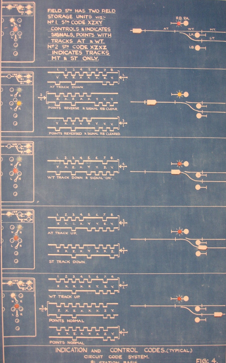
Thus, it will be noted that in one code both the new position of the points
and also the altered signal aspect are repeated and that the condition of
AT & WT track circuits are both checked in the same code.
The train now enters WT track circuit and an indication code is sent to
the office to indicate the fact. It will be observed that as the siding
signal has now assumed the step aspect this information is also repeated
in the indication code (Z on the 7th impulse).
It should now be clear that the composite type of code used in the circuit
code system effects very considerable saving in codes and in consequence
greatly reduces wear and tear of the apparatus, and the time of line occupation
as compared with systems in whioh a separate code must be sent to indioate
and control each individual function.
It will be noted, in the codes illustrated, how each code contains the
panel or station selection impulses on the 2nd, 3rd, 4th & 8th steps,
and how, in the indication code sent back when the train occupies ST track
circuit, the panel selection is altered from XZXY to XZXZ when sending from
No.2 Field Storage Unit instead of No.l Field Storage Unit.
------------------------
CODE ACTION,
The code action is generated in the coding unit by the counting chain
T & R relays. When once this chain of relays has teen started they will
run through a complete cycle of operations provided that their associated
checking circuits permit. The checking circuits ensure that, first, the relays
associated with each step occupy their proper positions before the impulse
is put on the line and secondly that if some fault should occur to prevent
the proper code sequence, then the code action is stopped in so far
that as that particular coding unit is concerned.
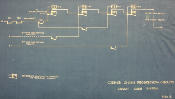
The chain relay circuit is shown on Fig. 5 and from this diagram
it will be observed that each relay when energized causes the relay circuit
in the rear to be broken and at the same time to energize the relay in advance,
so generating a continuous and progressive sequence provided that the checking
circuits (not shown in detail) permit this action.
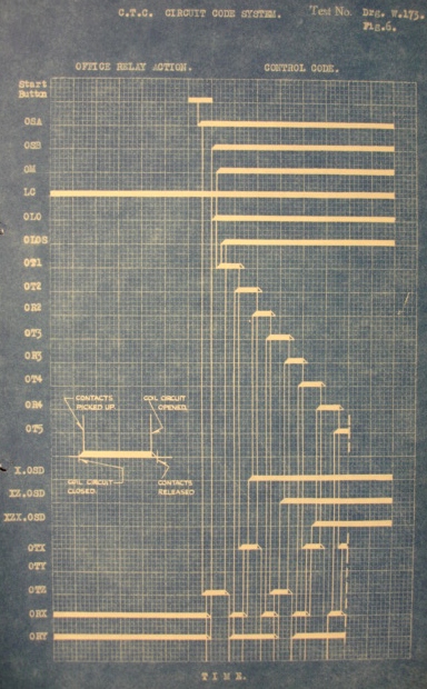
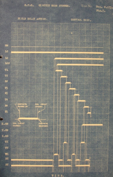
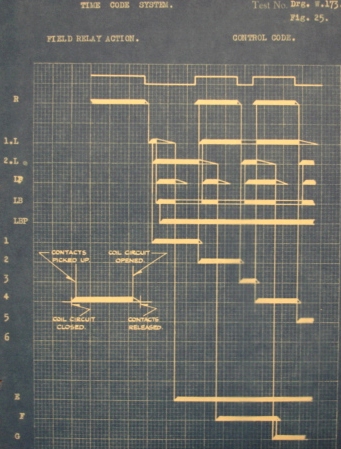
CODE RELAY ACTION.
The relay action for a typical control code is shown graphically on Fig.6.
and with the aid of this diagram the relay sequence can readily be followed..
The corresponding relay action in the field unit is given in Fig.7.
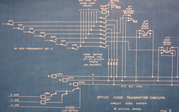
Examination of the chart Fig. 7 will show that each time one of
the T chain relays picks up one of the transmitter relays is energized and
in turn de-energizes one or both of the line relays. Thus, on the 2nd step
(see also Fig. 8) when 0T2 is energized the positive battery will
be fed over No.2 code setting jumper to the X bus line to pick up OTX and
so de-energizes the X line circuit. Similarly, on the 3rd, 4th & 8th
steps the character will be determined by the setting of the jumpers and
as shown on the figure the station selection characters will be XZXY. The
character of the 5th, 6th & 7th steps is determined by the position of
the push button and levers; for instance on the 6th step (when 0T6 is energized)
X character will be imposed on the line if the point lever is normal, but
Y character will be sent out if the lever is moved to the reverse position.
Only one control code can of course be transmitted at a time, so that one
set of chain relays and the three transmitter relays serve all panels, each
of which is connected in multiple to control the feed from the T chain relays,
over the particular starting relay of the panel which is sending, to the
XYZ bus lines.
Fig. 8 does not show the R chain relays but it will be clear from the
chart in Fig. 6 and the chain circuit in Fig. 5 that after the T chain relay
picks up the associated R relay will pick up to step the chain along to
the next T chain relay for the next step.
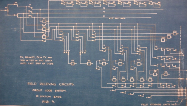
As has already been noted the line relays at each field location are in
series in the line, the impulses put on the line by the office transmitter
relays will be repeated at each field location, and reference to the chart
in Figs. 6 & 7 will show that the field RX, RY line relays and
TX, TY & TZ. transmitter relays operate in synchronism with their corresponding
office relays. Reference to the simplified circuit diagram on Fig.9 will
show that with the master relay M down (for receiving) the transmitter relays
TX, TY & TZ will follow the line impulses which are repeated by RX &
RY, and so X bus line will be energised for X line impulse, Y bus line Signal.
From the chart in Fig. 10 it will be observed that these relays together
with XSD are already energized when T8 picks up. Battery is now fed over
T8 front contacts from the Y bus line and over a front contact XSD to the
XY field storage unit where the delivery relay D is picked up. The final
stick relays in the storage unit, 5 YS. 6XS. 6TS. 7XS & 7YS. (see Fig.ll)
are now connected to the front contacts of the intermediate stick relays
and since 6X & 7Y are energized, 6XS which is already held by its
stick circuit, will be retained energized, the points remaining in the normal
position, while 7YS will be picked up to clear the Right Signal. The last
chain relay R8 now picks up and clears the line, and when both RX &
RY have picked up the slow release relay LO is de-energized. Finally R8 drops
away and so de-energizes the intermediate stick relays in preparation
for the next code.
Referring back to the 4th & 8th steps, it will be noted that these
are two which are used to determine which of the storage units attached to
the coding unit will be selected, & since X, Y or Z can be received on
each of these steps it follows that a maximum of nine field storage units
can be operated from one field coding unit.
So far only a control code has been considered, but each coding unit and
line unit is capable of operating either as a receiver or as a transmitter.
Thus, when the field unitse transmit en indication code to the office the
cycle of operations in the field is similar to that described for transmission
at the office end. The master relay M is energized and completes the necessary
connections to enable the field coding unit to transmit and as the chain
relays progress the character of the indication code impulses is determined
by code setting jumpers and by the position of the signal and point indication
relays (instead of levers and push buttons) over a similar set of chain
relays as shown for the office transmission on Fig.8. In the same way reception
at the office is carried out on exactly the same principles as has been described
for reception at a field location.
Synchronized action between a transmitting unit and a receiving
unit is obtained by the presence of a check circuit by which the line
at the receiving station is held open by the transmitter relay last
energized until the R chain relay picks up. Thus while the transmitter
relay at the receiving station is energized the R line relays in that line
cannot pick up again so that an impulse must register at the receiving station
and then pick up the R chain relay, de-energize the transmitter relay and
so finally allow the line to close.
This check or line lock action is illustrated on the charts in Figs. 6
& 7, on the 4th step. Here it will be noted that the line is
held open by TX in the field while XSD & R4 pick up. Relay OTX
at the office has dropped out but the office chain does not progress until
TX releases upon the pick up of R4, and permits GRX & RX to pick up together.
The diagrams have been simplified as much as possible to try to
give the reader a clear understanding of the basic principles upon which
the Circuit Code system operates. Additional circuits are provided,
however, which ensure that faulty operation of a unit will not result in
the standard outside relays of the relay interlocking circuits receiving
controls not intended by the Operator & also so that a faulty unit will
not interfere with the correct operation of units at other locations.
The principal features of the System have now been dealt with but there
remain several important auxiliary features, some of which assist in the
speed and convenience of operating the system and others which must be understood
in order to be in a position to deal with a possible failure on some part
of the signalling equipment.
Code Lamps.
Two yellow lamps are provided on every control machine one of which is
illuminated during the transmission of a control code and the other during
the reception of an indication code. The indication code lamp is also connected
in such a way that it will become illuminated should an open circuit occur
in the line circuit.
Cancel.
If for any reason it is desirable to cancel control codes which have been
stored at the Office, operation of the cancel button will destroy all storages
which have not already been transmitted.
A fault on the system may become apparent by reason of continued code
action, and the code indication lamps will indicate in these circumstances
whether the trouble originates on an indication code or on a control
code. If this repeat code action occurs on an indication code, a time delay
relay in the field will stop the code after about 25 seconds.
If the control code is at fault, code action can be stopped by pressing
the cancel button, and the individual panels can then be tried one at q time
in order to locate the difficulty. If the trouble is local to the
particular panel, then other panels can be used is needed, independently
of the defective panel.
Control codes can be stopped instantly at any time before completion by
operating and holding in the start button. The operation of depressing the
start button automatically creates a new storage. Thus in case a code for
a given set up in the field is initiated and a change of plans is desired,
the code action can be stopped at once, the panel set up changed, and the
code immediately sent out upon the release of the start button. In case it
is desired to cancel the code entirely the start button should he held in
until the cancel button is operated and both buttons then released in the
same sequence. This operation will also cancel all other storages.
Recall.
All indications received at the Office are entirely independent of the
control apparatus and are responsive only to changes in the field indication
circuits. All indications are continuos and any change of conditions in the
field is immediately reported to the Office.
The Operator can, however, check any or all of the indications showing
on the control panel, by utilizing the recall feature, which consists of
simply pressing the start button of any selected panel. Since no change
of lever position has been made the panel will remain dark, a second operation
of the same start button will recall (and re-check) all indications relating
to that start button. In the same way if a control code is transmitted
and no change in the field apparatus results due either to field locking
as already described under the heading of "locking" or to faulty operation
of some portion of the field apparatus a dark panel will be obtained. In
this case also a second operation of the start button will recall all indications
which when obtained will report the position of the signal, points, etc.
Storage.
Should the start button be operated to transmit a control
code to the field while an indication code is being sent in, the control
code is stored and will he sent out immediately the line clears, without
another operation of the start button. Additional storages may
be made, up to the number of start buttons provided on the control
machine. Furthermore, the start buttons may be operated in quick
succession at any time and control codes will follow each other until all
control storages have been run through.
In the same way storages are made in the field should the line be busy,
and stored indications will be sent in directly the line clears.
Code Repeat.
The coding circuits are arranged so that should a coding unit be unable
to complete the whole code action the repeat action takes place and thus
gives the unit in trouble a chance to clear a difficulty which may
be only temporary. The code repeat feature is also of use since it gives
the equipment every opportunity of delivering a code which might otherwise
be lost. If the fault remains, then the repeat can be stopped either by using
the cancel button, or by the Time Delay Relay in the field.
---
---
code and re-set the equipment for the next code.
It is important to note that a long impulse is always used to register
information, and a short impulse to stop the counting chain and convey
the absence of information.
The seven station or panel selection steps must always contain three long
impulses and four short impulses, and by arranging to vary the position of
the long impulses in this group, selection can be obtained for 35 stations
and panels.
Thus as in the Circuit Code system, the codes are of a composite nature
and each code contains the selection impulses as well as impulses for the
control or indication of the field functions. The actual formation of the
complete code is controlled by the position of the office code setting jumpers
and the levers in the case of a control code and by the code setting jumpers
and the positions of the local field relays for an indication code.
Chain Circuit.
The line impulses are generated and received by the counting chain relays
1 to 8, the principle of the counting chain may be seen by referring to Fig.
22. The fourth impulse is shown and relay 4 is shown stuck up
over the front contact of the line repeater relay R. The next operation is
the release of R which breaks the stick circuit for relay 4 and also applies
battery to relay 5 over back contact of relay 3 and front oontact of the relay
4. Relay 4 will remain up for a short time due to the delay action of rectifier
3 and for sufficient time to allow relay 5 to pick up. As soon as relay
5 picks up, the rectifier circuit to relay 4 is broken and this relay then
drops away. It will thus be seen that relay 4 is rendered slow release
only until it has served its purpose after which it is immediately released.
The next operation is the picking up of relay R. This breaks the feed
for relay 5 and energizes relay 6 over a back contact of relay 4 and front
contact of relay 5. Relay 5 is rendered slow release by rectifier 2 until
such time as relay 6 picks up when relay 5 will release. It will thus
be clear that the counting chain action is a continuous sequence.
From Fig. 20 it will be observed that all R relays are normally
energized but will be de-energized when one of the T transmitter relays pick
up.
The line impulses for any particular station are generated by a back contact
of the T relay. The character of each impulse is determined by the
interval of time which this contact holds the line open or closed. The
operation of the T relay is outlined in Fig.21. Normally the T relay is alternately
picked up and released by the odd numbered chain relays 1-3-5-7
to generate the short impulses. When selection requires that
the line be held open for a long impulse, positive battery is applied to
the stick circuit for T and it remains up until relays 1L & LP release.
In the same way when a long closed impulse is required, relay T must be held
down for a "long" period. Relay T is therefore held down by means
of a circuit which applies +ve battery to both terminals of the relay. The
stick down circuit is maintained until relays 2L &. LP release, thus
timing the long closed impulse as for a long open impulse.
In this way the series of long and short impulses which forms the complete
code is generated by the counting relays and the character of each impulse
so generated is determined by the circuits connected to relay T, which
circuits are in turn selected by the code setting panel or station jumpers
and by the position of the levers or field local relays.
Before going further the action of the slow release relays 1L, 2L, LB
and LBP must be considered and the circuit for these relays
is shown on Fig. 23. During code action all relays are energized,
but the relays are timed so that 1L and 2L bridge the time of a short impulse
but will not bridge a long impulse. It can thus be seen that
if the relay R remains energized for a long impulse relay 2L will release
while if R stays down for long impulse relay 1L will release and in this
way these relays when receiving select between short and long impulses.
Either 1L or 2L releasing will de-energize LP, the function
of LP being to add a short additional delay to the release time of 1L. or
2L when one of these relays is holding the transmitter relay T up
or down for a long impulse. Thus the unit which is transmitting provides
a small additional delay to a long impulse to ensure that all stations whioh
are receiving the code have ample time to release their 1L or 2L relays as
the case may be. The LB and LBP relays serve to protect the unit from line
interference and to reset the unit in the event of such trouble.
|
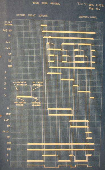
The code action thus far described may be seen in Charts Fig. 24 & 25. |
When no transmission is taking place each coding unit is set to receive a code and
before it can transmit, the master relay M must
be energized and Chart Fig.24 shows that this relay picks up immediately
the starting relay ST becomes energised. The same principles apply to
the field equipment and the M relay will pick up directly the starting relay
is energised by a change in the position of the local indicating relays.
With the master relay up the code will progress to the eighth step - that
is, the counting chain will complete one cycle of operations. At the end
of this cycle, if on a control code, one of the field stations will have
been selected ready for the reception of the information (controls) contained
in the next part of the code. If it is an indication code the office apparatus
will have followed the transmitting field station and the storage bank; corresponding
to the field station will be selected in readiness to receive the information
(indications) in the remaining code steps. Immediately the 8th counting
relay is reached a new cycle begins at No.l. counting relay, to transmit
the controls or indications to the receiving station. The complete code action
is entirely automatic and reference to Charts Fig. 24 - 26 will help to sake
the transmitting and receiving notion clear.
 It should be noted however, that as there are only 14 impulses in a control
code the second cycle of counting relay operations progresses only as far
as No. 5 relay when all the controls will have been transmitted and the equipment
will set for any further code action.
It should be noted however, that as there are only 14 impulses in a control
code the second cycle of counting relay operations progresses only as far
as No. 5 relay when all the controls will have been transmitted and the equipment
will set for any further code action.
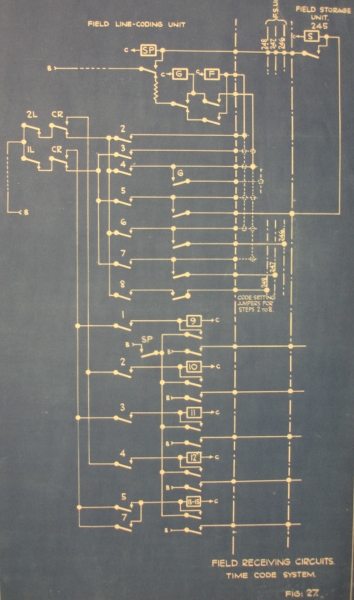
As the 2nd cycle proceeds at the receiving station the information registered
on the long impulses is stored on the intermediate stick relays 9, 10, 11,
12 and 13-15. This action can be followed from Fig.27; as already
stated when a station is receiving the slow release relays 1L and 2L select
the long closed and open impulses respectively. Thus on the 10th step
(which will be a "closed" impulse) if 2L drops away due to the impulse being
long relay l0 will be picked up over a front contact of No2. counting relay
and will remain up through a common stick circuit over a front contact of
SP. Similarly if the 11th step (which will be an "open" impulse) is
long, relay 1L will be de-energised end in so doing will energise relay
11, to store the Information on this relay. If the 10th step had been a
closed short impulse conveying the absence of Information, then the
delay action of relay 2L would have bridged the short impulse, in
so doing would not cause relay 10 to pick up on this step.
PART IV
The foregoing sections deal with the principles of the systems and
with the Code Equipment itself, and it is intended to conclude with
one or two brief notes which will, it is hoped, assist in the consideration
of the application of C.T.C. to any particular stretch of road.
Considering first the Circuit Code System, it was mentioned earlier
in the Description that the allocation of codes given on page 18. was typical,
and that it could be varied at will; thus, in planning the number of
field storage units which will be required to handle the controls and indications
at any particular field location, it may be found that there are more signals
to be controlled than there are points, in which case one of the units may
be connected so as to control & indicate signals on both the 6th &
7th steps
It may also happen that the number of track circuits to be indicated
may total more than can be handled on the 1st & 5th steps of the available
code, and the additional indications may then be set on the 6th or 7th code
step of any unit which has one of these steps spare. If no spare steps
are available, an additional unit will have to be allowed, and it is
then capable of sending one, two, three or four indications as required.
If it should happen that after accounting for all apparatus to be controlled
and indicated a unit has still an unused code step, this is set to
X or Y by connections on the unit rack and may be regarded as a true spare,
since it can be very easily utilized at any future date after the equipment
is in service by simple alterations to the external wiring and the
addition of the necessary levers A/or indication lamps on the control machine
front panel.
As has been previously explained in Part II one Field Coding Unit
will control from 1 to 9 Field Storage Units.
The extreme cases of a full 81 station system would be 81 locations with
1 line Unit, 1 Coding Unit and 1 Storage Unit at each, or 9 locations with
1 Line Unit, 1 Coding Unit, and 9 storage Units at each.
The overall sizes of the units are shown on Drgs. W.194, 4-6, and they
may conveniently be grouped on a suitable rack in the relay hut.
The circuit diagram (Fig. 11) shows the arrangement of connections to
the field storage unit, the diagram on the left showing suitable circuits
when using the typical code allocation on page 18. while typical alternative
connections are shown for other node allocations such as control of points
on the 7th step, track indications on the 6th & 7th steps,
etc. The list below gives a few of the more usual functions which may be
controlled or indicated on the various steps —
1st Step.
Indicate — Track Circuit
(clear, occupied) - Air pressure or voltage (high, low) - Lights (in, out)
- Signals (on, off) - Fog, or No Fog - Leakage Indication (clear or fault)
- Ground Frame (locked, unlocked) - Traffic Direction (Eastbound or Westbound).
5th Step.
Indicate -- As for 1st Step,
Control —Approach Lock Release
- Call-on Signal - Auto or Non-Auto operation of Signals - Fog Repeaters
(on, off) - signal Lights (in- out)-to Cut-in Indications not normally
required - Ground Frame (Release, Lock) .
6th Step
Indicate -- Points
(normal, Open & Reverse) - Signals (Left or Right Off or All on)
or 3-position semaphore 0°, 45°, 90° - (or 2-position semaphore
0°, 90°, or wrong). Also as for 1st step.
Control — Points (N, R)
- Signals (L or R Off or All on) and also as for 5th step.
7th step.
Indicate — As for 1st &
6th steps.
Control — As for 5th & 6th
steps.
A knowledge of relay interlocking circuits and consideration of Fig.11
will then enable the number of relays required at each location to be estimated.
All relays and circuits controlled by the final stick relays (5YS, 6 XS,
6YS. 7XS. 7YS) in the field storage unit should be operated by direct current
at 24-v. and similarly the indication circuits from the track relays signal
and point indication relays, etc. should be 24-v. D.C. although the
relays themselves may be of either a D.C. or A.C. type.
PART V.
Reference to page 28 will show a typical allocation of code steps
for a station controlled by the Time Code System, but in planning a layout
it may be found desirable to use certain steps for purposes other than those
stated.
For instance, it may be found that the number of signals to be controlled
exceeds the number of points, or that there are more track circuits than
can be accommodated on the 9th & 11th steps of the available codes
and in these cases code positions other than the typical ones given on page
28 can be used for these functions.
For example, steps 9 -11 can be used for signal control and Steps 12 &
14 can be used for track circuit indication. Many of these variations are
shown on Fig. 28, but this by no means exhausts the possible use of
the various steps, and some further suggestions are given in the table below.
Indication Code Step 9 or 11.
Track Circuit (clear, occupied) - Air Pressure -Voltage (high, low) - Lights (in-out) - Signal (on-off) -Fog or No fog - Leakage indication
(clear or fault) -Ground Frame (locked-unlocked) - Traffic Direction
Eastbound or Westbound).
Control Code step 13.
Approach Lock Release - Call-on Signal - Auto or Non-Auto operation of
Signals - Fog Repeaters (on-off) -Signal Lights (in-out) - to
cut in indications not normally required - Ground Frame (Lock-Release).
Control code steps 9 & 11.
Points (N, R) - Signals (L or R off or all on) - also as for step 13.
Control code steps 10 & 12.
As for steps 9 & 11, and step 13.
Indication Code steps 13 & 15
Points (Normal, Open &. Reverse) - Signals
(L or R off or all on) - 3-pos. semaphore 0°, 45°, 90°.
- 2-pos. semaphore 0°, 90° or wrong - also as for Steps 9 or 11
Indication Code Steps 10. 12 &
14.
Signals (L or R off, all on, or wrong). Also as for steps 13 & 15
and steps 9 or 11.
Thus the controls & Indications may be distributed to give the minimum
amount of code apparatus at each location, and if it is then found
that there is still a code step unused, this can be regarded as
a spare, and it can be very easily utilized at any further date
after the equipment is in service by simple alterations to the external wiring
and the addition of the necessary lowers &/or indication lamps on the
control machine front panel.
The available station call signs are divisible into the following groups
——
234 245 345 256 356 456 267
235 246 546 257 357 457 268
236 247 347 258 358 458
237 248 348
238
367 467 567 278 378 478 578 678
368 468 568
and any number of field storage units from one up to the maximum
number in the group can be controlled from one field line-coding unit
having the code of the first two figures of
the group.
E.g. F.L.C.U. No.23 can control 5 field storage units
« 45 " 3 "
" 56 " 2 "
" 27 " 1 "
It should also be noted that one combination, say 234, may be used
at one location and the remaining combinations of the group at other locations
with separate line-coding units.
The overall sizes of the units are shown on Drgs..W.194, 21 to 24 and
they may conveniently be grouped in a suitable rack in the relay hut.
The circuit diagram (Fig.28) shows the arrangement of connections to the
field storage unit, the diagram on the left showing suitable circuits when
using the typical code allocation of page 28 while alternative connections
are shown for other code allocations, such as control of points on the 10th
- 12th steps, track indications on steps 10, 12, 13, etc.
A knowledge of relay interlocking circuits, and consideration of
Fig. 28 will enable the number of relays required at each location
to be estimated. All relays and circuits controlled by the final stick
relays 13P, 9P, 11P. 10P. 12P. should be operated by direct current at l6-V
and similarly the indication circuits from the track relays, signal
& point indication relays etc. should be 16-V. D.C, although the relays
themselves may be of either a D.C. or an A.C. type.
PART VI
When the number of field locations, and the number of units at each location
has been determined in accordance with the principles outlined in Part IV.
or V., the layout of the control machine front panel can bo considered.
It is obviously not possible to give an exact size for the control machine
as it may vary on account of many different factors. As a guide, however,
it can be taken that the minimum dimensions are
Length 3'-0". Height 5'-4".
Depth 1*-7".
The usual horizontal spacing of levers (or panels) is 2 1/2" or 3", but
this is sometimes increased so that levers may for ease of manipulation
be placed as nearly as possible below their relative positions on the track
diagram above them. Then again, if for instance two pairs of
points are controlled from one panel (i.e. one start button) both
point levers could be placed in the top row. Space also is often allowed
for further extensions of the system, in which case the front panel
is drilled and provided with suitable plugs which can be removed when the
levers are fitted.
Thus it will be seen that although the height and depth of the machine
will not in the ordinary way vary from those given above, the
length will depend upon the actual scheme, 5 feet probably being about the
average.
There is another factor which may alter the overall dimensions,
the provision of an Automatic Graph Recorder. When this instrument
is fitted, the desk shelf is made several inches wider to acommodate the sliding
glass plate over the chart. The weight of a control machine complete
with Office Line, Coding and storage Units la not great and any sound,
well-built floor should carry a C.T.C Control machine of practically any
size without strengthening or other special provision.
Referring now to power supply, the office and each field location
will require a direct current supply, preferably obtained from storage batteries
trickle charged from a metal rectifier set. The voltages required are 24
for the Circuit code system, and 16 for the Time Code System. An additional
battery and trickle charger is required at the office to supply power for
the line circuit. he capacity of the local batteries will of course
depend upon the number of unite at the location and also upon the number
of other relays to be supplied from the battery. As a guide, however,
it has been found that batteries having a capacity of 75 to 100 ampere-hours
are sufficient. For trickle charging these a combined trans former-rectifier
set is recommended such as the B.P. type.
Constant current is maintained in the line circuit and the voltage is
increased according to the number of line relays required, and to the resistance
of the line wires. The drain on the line batteries is small, so that
a line battery of quite low capacity, say 20-25 A.H. is sufficient.
Storage batteries are recommended in order to maintain a constant D.C.
potential, as also to carry over during a failure of the main power supply.
It often happens, however, that a power supply failure would also cause a
shut down on A.C. relays and other apparatus, and in this case the only function
of the battery is to prevent wide fluctuations of D.C voltage. If it is
found that the supply voltage can be regularly maintained within narrow
limits it would be possible to dispense with batteries and supply the D.C.
for line and local purposes direct from rectifier sets.
The control machine indication lamps are fed direct from an indication
transformer which may form part of the control machine equipment or may be
placed in some other convenient position. If the C.T.C. installation
is operated on direct current, and the field apparatus (signal relays &
track circuits, etc.) are not de-energized in the event of a power
supply failure, then a cut-over relay is provided at the office to transfer
the indication lamp supply from the transformer to the local battery.
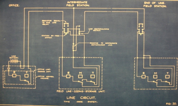
It la usual to carry the line wires on poles rather than in cable,
partly since a pole line is generally less costly, at any rate for
installations over 5 or 6 miles, and partly as the possibility of trouble
due to inter-line capacity is reduced to a minimum. The line
construction should be such as to reduce possible leakage losses to a minimum,
especially on long circuits, adequate lightning protection must
be provided, and sectionalizing and station bye-pass switches and resistors
are desirable to enable a field location to be switcher out of
circuit in the event of failure, or for maintenance purposes.
The wires can be carried on the same poles as other signalling circuits and
it has been found that C.T.C. lines give practically no interference on any
adjacent telephone circuits.
In some installations however, notably those on 'Tube'
or 'Underground' railways, cable must be employed for the line circuit and
special precautions are then taken to balance out the effects of capacity
between lines, either by the use of special code units, or by other means.
APPENDIX A.
C.T.C. DEFINITIONS
Office. The building or
room which contains the control machine in a C.T.C. installation.
The machine may be placed in a signal box, Train Controller's or Dispatcher's
Office, or other convenient place, not of necessity situated
close to the Railway.
Field Station. A concentration
of signals and points to be controlled by the Operator at the office and
located at some distance therefrom.
Control Machine. The Operator's
Office equipment comprising the necessary levers, indication lamps
and relay units to enable him to maintain control of the signals and points
at each of the remote field stations under his supervision.
Code Units. The units which contain
the code relays that generate and de-code the line impulses.
Control Code. An outgoing
code from the Office Control Machine containing "orders" or "controls"
to effect some alteration in the position of the points ex signals at one
of the field stations.
Controls. Those impulses
in the complete code which are used for the control of point end signal relays
in the field.
Indication Code. An incoming
code from one of the field stations containing "indications" of the condition
and positions of the field signalling apparatus.
Indications. Those
impulses in the complete indication code which repeat and indicate to the
Operator the positions of the field apparatus.
Impulse or Step. An interruption
of one or both of the normally closed (or energized) line circuits.
Impulse Character The
character of an impulse or step refers to the line or lines opened on any
step, i.e., X line opened, or Y line opened, or Z both lines opened.
APPENDIX B
Circuit Code Relay Nomenclature.
ORX. ORY. RX &
HY. The Line Relays ORX. ORY, RX & RY are known as
repeating
relays. That is, if a station is receiving, its line relays repeat the
impulses which are on the line and if the station is transmitting its line
relays repeat its transmitter relays
OTX. OTY. OTZ. TX. TY &
TZ. The transmitter relays OTX. OTY. OTZ. TX. TY &
TZ indicate their function. If a station is sending, they generate
the impulses and transmit them to the line and if
a station is receiving, they transmit the impulses from the line
to the coding unit.
OM. M & M1 The relays
OM. M & M1 are known as master relays. They energized if the station
in which they are located is sending, and de-energized if the station is
receiving. Their purpose is, therefore, to determine if
the station will send or receive
0LC & LC. The
0lc & LC relays are slow release relays and are known as line closed
relays since they receive energy when the line is closed. They serve the
purpose of bridging the open periods of the line. They have an additional
function of cutting a station out if, for any reason, it cannot receive an
impulse.
OLO & LO.
The OLO & L0 relays axe slow-acting relays and are called
line open relays since they receive energy when the line is open. Their
purpose is to bridge the closed periods of the line during a code,
and to serve as a lock so that a station cannot cut in on the line
when it is busy.
OLOS & LOS The
OLOS & LOS are line open stick relays. Their purpose is to ensure
that other stations will be ready to receive before a station starts transmitting.
That is, a station may receive with its LOS up but it may not transmit.
These relays are also slow-acting.
0T1. Tl. 0T2. 0T3.
0T4. T4, etc. 0T1 & Tl are the
chain transmitter relays. Their purpose is to prepare a station, on
successive closed periods of the line, for the following impulse regardless
of whether the station is sending or receiving.
0R2. R2. 03R. R3.
etc. These relays are chain release and progression relays.
They receive energy on successive open periods of the line and serve to release
the T relays of the chain as well as the transmitter relays of the line
unit.
XSD. YSD. & ZSD. These
relays are station determining relays and pick up
on the fourth step of the code and on the impulse indicated by the prefix
letter. Their name indicates their function.
D The D relay is known
as the delivery relay. It picks up at the end of each control code
and delivers the functions stored in the intermediate stick relay
to the final stick in the field storage unit. It is dropped when the
LO drops.
OD & 0D1.
These are office delivery relays and operate on the last step of an
indication code to deliver information to the indicating relays.
SA & OSA.
The SA & OSA relays are known as starting or storage relays. If
the line is not busy at the time they are energized in order to initiate
a code, they serve as starting relays and if the line is busy when they
are energized, they serve as storage relays. That is, they store their
starting circuit until a time when the line can receive the code which they
initiate.
SB & OSB. The
SB & OSB relays are also starting relays. They pick up after the
SA or OSA and connect the code, which is set up to the line and coding
units so that it will be
transmitted.
APPENDIX C.
Relay Nomenclature. Time code system.
R The R relay is
known as the line repeater relay. This relay repeats the line impulses at
each station for the purpose of operating the station coding equipment.
T The T relay is
the line transmitter relay and transmits the code to the line.
1L 1L is the Line
open alow release relay. At the transmitting station this relay produces
the long "open" (odd numbered) impulses and at the receiving
station it causes these impulses to be registered.
2L 2L is the
Line closed slow release relay. At the transmitting station this relay
produces the long "closed" (even numbered) impulses and at the
receiving station it causes these impulses to be registered.
LP This relay is
the slow release repeater of 1L and 2L relays. On transmission this
relay produces the time element margins necessary to ensure registry of
the long impulses at the receiving station.
LB & LBP. LB
& LBP are the slow release impulse bridging relays.
These relays in combination bridge the normal open and closed periods of
the line to permit normal code action.
F F is the first
group selecting relay, which operates on the impulse number by which
it is prefixed, 2F, 3F, 4F
G G is the second
group selecting relay, which operates on the impulse number by which it is
prefixed, 24G, 25G, 26G etc.
S Relay S is the
Station selecting relay, which operates on the impulse number by which
it is prefixed, 234S, 235S, 236S, etc.
FP This relay repeats any
one of the five F relays in the office storage group.
GP This relay repeats any
one of the fifteen G relays in the office storage group.
SP This relay repeats any
one of the thirty-five s relays in the office storage group.
MEP MEP is a repeater of
M and B which connects the office code selecting relays ST, G and F to the
coding unit for transmission of the F selecting impulse.
AK, TK, NWK,
RWK, LHGK, RHGK, RGK These relays
are known as the indication stick relays. They directly control the
indication lamps and train graph pen magnets.
MSP. This relay is a repeater
of M and S which connects one group of wayside indication circuits to the
coding unit for the transmission of indications from the field to the
office.
9P, 10P. 11P,
12P, 13P. These are the final stick relays which are
picked up at the end of the control code if the step of corresponding number
is long. They are energized over the D relay and the intermediate
stick relays 9, 10, 11, 12, 13 - 15, and control the relays in the
external circuits for point and signal control etc.
CTC
Startsidan
Sidan uppdaterad den 17 december 2005